Fun With Shift Registers
A tutorial to help you understand how a shift register works.Steps
Categories
Created by takide
Status: Active
Status: Active
Step 7: Bit 5 Step 11 of 12
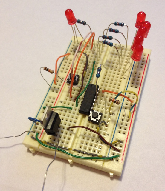
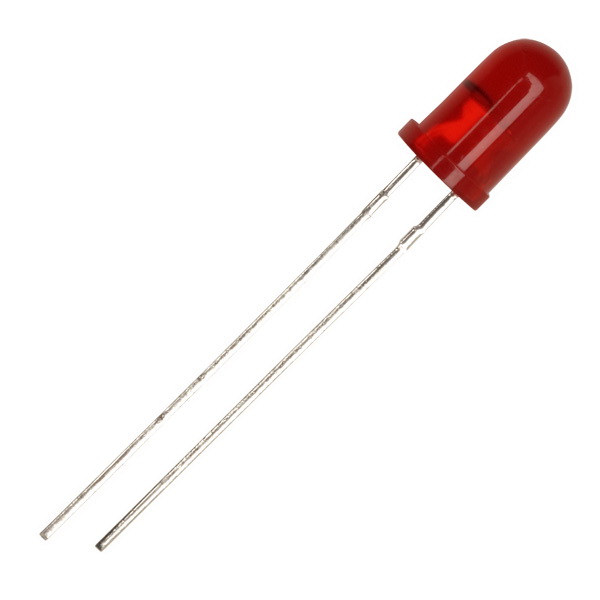
Add one more LED to the row of LEDs as we did before. Then, I used a 560 Ohm resistor to go from output bit 5 on the shift register to the unconnected end of the LED as shown in the picture. The output pin for bit 5 is right above the clear pin on the right side of the IC. (The clear pin was the one that we pulled to the 5v rail in a previous step.) If you are unsure where the output pins are for a certain bit on the IC, refer to the diagram in the step titled: "Getting to know the 74HC164".
