Fun With Shift Registers
A tutorial to help you understand how a shift register works.Steps
Categories
Status: Active

Fun With Shift Registers Step 1 of 12
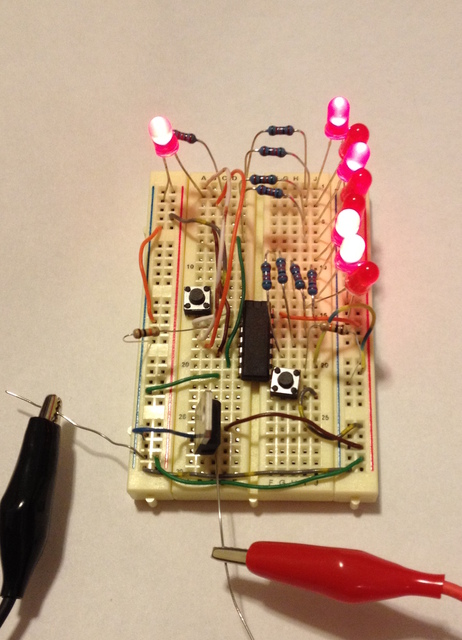
Shift registers are one of the basic building blocks of integrated circuits and computers. If you're like me, you may have found yourself running out of pins on your microcontroller. Sometimes you might want to control a lot of LEDs or other components but you may not have enough pins to control them individually. You may consider buying a more powerful microcontroller but wait - shift registers to the rescue!
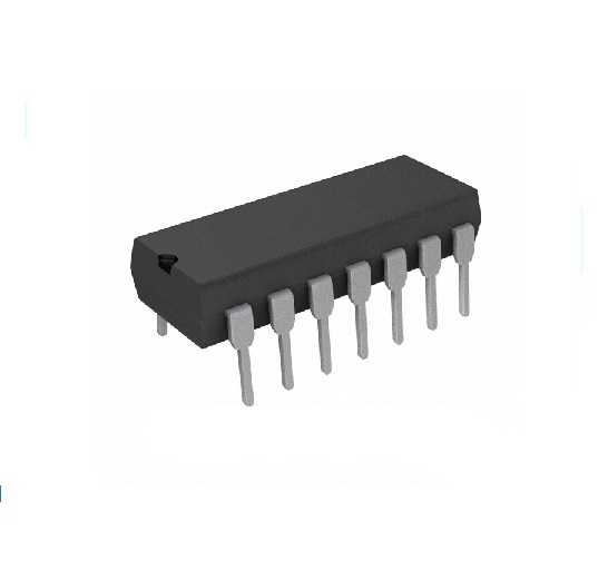
In a nutshell, a shift register has two inputs: A data input and a clock input. In addition to that, shift registers will often have 8, or 16, or sometimes up to 64 outputs! The 74HC164 shift register that we will use in this tutorial has 8 outputs, or output bits. Each of these outputs can be high or low, or in binary, 1 or 0. This makes it easy to drive lots of LEDs or other components with very few inputs.
When the clock pin goes high, the shift register "shifts" the 8 bits over one place. At the same time, the shift register copies the value data input to the first bit in the shift register. To shift in more bits of data, the clock pin must go low, and then high again with another bit of data in the input.
For example, lets imagine that our shift register has the following bits of data already in it: 10011001 (With the 1st bit on the left, and the 8th bit on the right.) If the data input is 1, and the clock pin goes high and then low, it will shift the bits one space to the right and copy the 1 from the input into the first bit. Now the output will be this: 1100110. Notice that the last, or 8th bit, disappears because there is no place to shift it to.
Parts List:
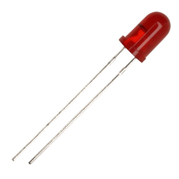
- (9) 5mm LEDs (Any Color) (A-1554)
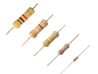
- (9) 560 Ohm Resistor (A-2065)
- (2) 10K Resistor (A-2253)
- (1) 74HC164N Shift Register (A-922)
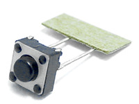
- (2) Tact Switch (A-5144)
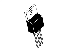
- (1) LM7805 5v Regulator (A-179)
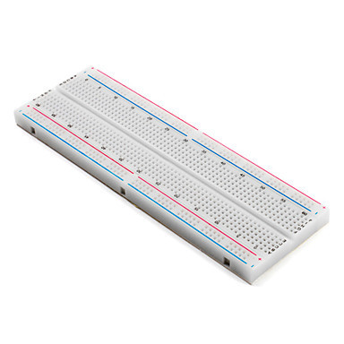
- (1) 400 Point Solderless Breadboard (A-1424)