Fun With Shift Registers
A tutorial to help you understand how a shift register works.Steps
Categories
Status: Active

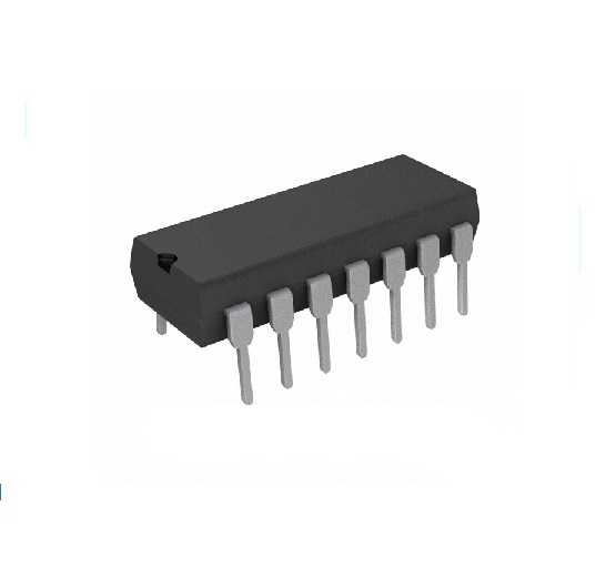
Getting to know the 74HC164 Step 2 of 12
Datasheets can be overwhelminmg to read sometimes. But, when broken down piece by piece, they become quite easy to understand.
Here is what the pinout for the Shift Register Looks like:
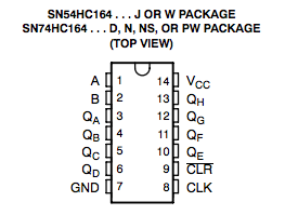
You should notice that there is a label next to each of the 14 pins on the IC. Here is what each of the labels represent:
Pin "A"
Pin "A" is one of the inputs. If it is high, a "1" bit will be shifted into the shift register when there is a clock pulse. Similarly, if it is low, a "0" bit will be shifted into the shift register when there is a clock pulse. There is a slight catch on the datasheet though: The "A" and "B" inputs are in an AND gate. This means that for data to be shifted into the shift register, both "A" and "B" must be the same. (Both high, or both low.) If they are not the same, data will not be shifted into the shift register.
Pin "B"
Pin "B" is essentially the same as pin "A". This pin must be the same as pin "A" for data to be shifted into the shift register properly.
Pins "QA" to "QH"
These pins are the outputs of the shift register. There are 8 output pins, thus this is an "8 bit" shift register. Each of these pins will go to a LED to show the value of each bit in the shift register. When the bit is high, it will light the LED. When the bit is low, it will leave the LED unlit.
Pin "GND"
This is the Ground or Negetive pin of the shift register. This pin is connected to the negetive terminal, or black wire, of the power supply.
Pin "VCC"
This is the voltage pin. This is connected to the positive terminal, or red wire. of the power supply. This chip has a maximum voltage of 6v, so we will need a regulator to power it off of 9v or more.
Pin "CLK"
This is the clock pin of the shift register. When this pin is high, it tells the shift register to shift all of the bits over one place. For example, if the current values of each bit in the shift register were: 01101001 the clock pulse would shift all of the bits 1 place to the right: X0110100 where X reoresents the current value of pin "A", the input pin.
Pin "CLR"
This is the clear pin. When this pin is pulled low, it will clear the current values of all of the 8 bits in the shift register. We will not be using this pin in this tutorial, so we will just tie it to high.
Hopefully this made the shift register easier to understand. If you are still having trouble understanding the shift register, don't worry; It will make more sense when you build it!