Categories
Created by takide
Status: Active
Status: Active

Part 2: Building the Flasher Step 4 of 5
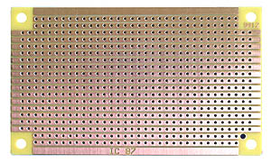
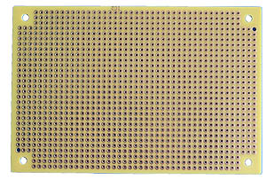
Now take out a peice of prototyping board. I used a peice that was about 2" wide and 1.5" tall. You may want to use a bigger piece if you are newer to soldering.
Here is the schematic for the flasher circuit:

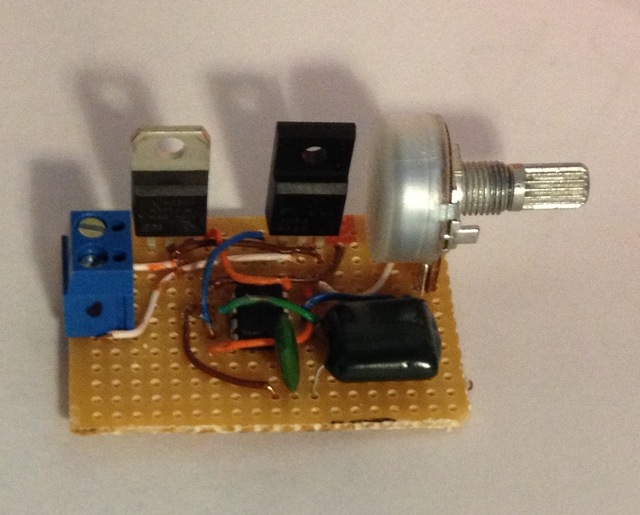
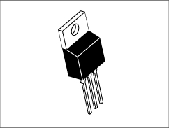
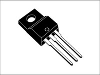
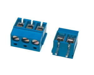
Begin by soldering the screw terminals, the 5v regulator, and the mosfet as shown in the schematic above. It will look something like this:

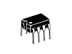
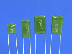
Then, solder the 555 timer IC and the 10nF and the 0.47uf capacitors.
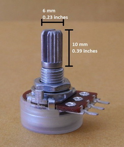
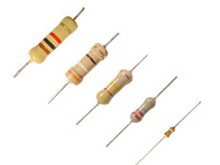
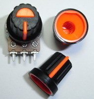
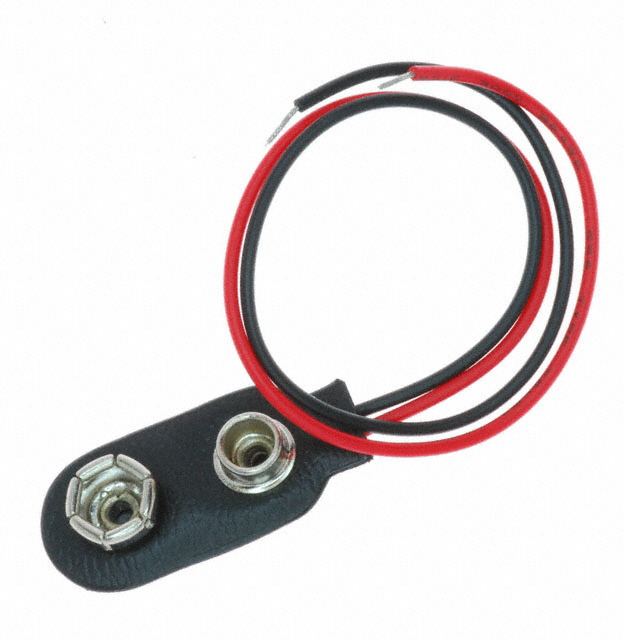
Lastly, solder the 9v battery clip, the 100K Resistor, and the 200K potentiometer.
Here is what the finished flasher will look like: