Status: Active

With great power comes great responsibility: Adding the ATmega328P Step 3 of 5
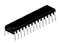
Now that we have power to our breadboard we can add the ATmega328P. Note for those that are new to integrated circuits the side with the round indent signifies the pin numbering.
How are there so many pins on an Arduino while there are only 28 pins on an ATmega328P? This is becuase the rest of the pins of an Arduino are power lines or duplicates. The photo below shows a matching of the Arduino Uno R3 Pins and the ATmega168P (which is the same pinout as the ATmega328P) pins.
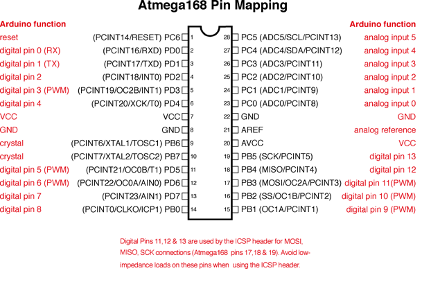
The important pins here are pins 9 and 10 for the crystal. Pins 19, 20, and 21 for the built in Arduino LED, the Voltage Reference, and the Ground respectively.
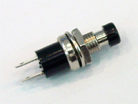
As well as Pin 1 for the reset button, which is important! DO NOT skip the reset button, we have to have a reset button to properly upload sketches.
In summary we need to attach
Pin 1 -> +5V via a 220 Ohm resistor.
Pin 7 -> +5V
Pin 8 -> Ground
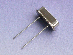
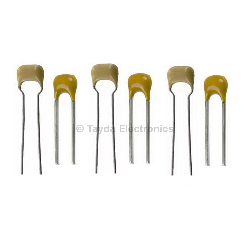
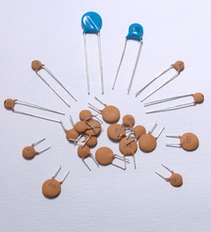
Pin 9 -> One side of the 16.00 MHz Crystal -> ground via a 22pF Capacitor
Pin 10 -> The other side of the 16.00 MHz Crystal -> Ground via a 22pF Capacitor
(The crystal should bridge pin 9 and pin 10)
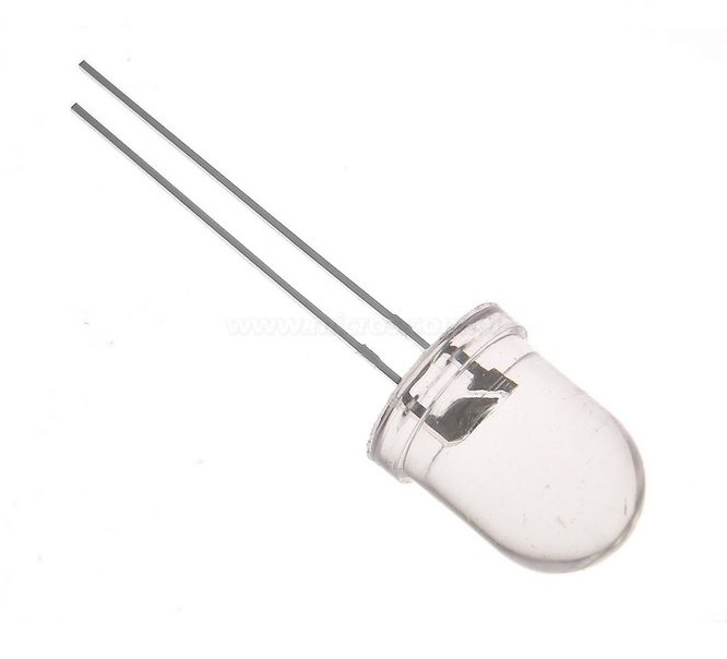
Pin 19 -> LED (hook the pin up to the positive side, then ground the LED via a 220 Ohm Resistor)
Pin 20 -> +5V
Pin 21 -> +5V
Pin 22 -> Ground
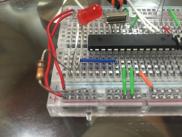
A photo of the crystal grounded via 22pF capacitors as well as pin 7 and pin 8 hooked up properly.
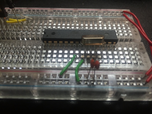
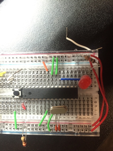
This shows the other side of the ATmega328P
Pin 19 to an LED via the blue jumper. The LED is grounded with a 220 Ohm resistor. (The exact value of the resistor doesn't matter too much here it just needs to be grounded via a resistor.
Pin 20 is a green jumper to +5V.
Pin 21 is the other green jumper that goes to +5V.
Finally Pin 22 is grounded via the orange jumper.
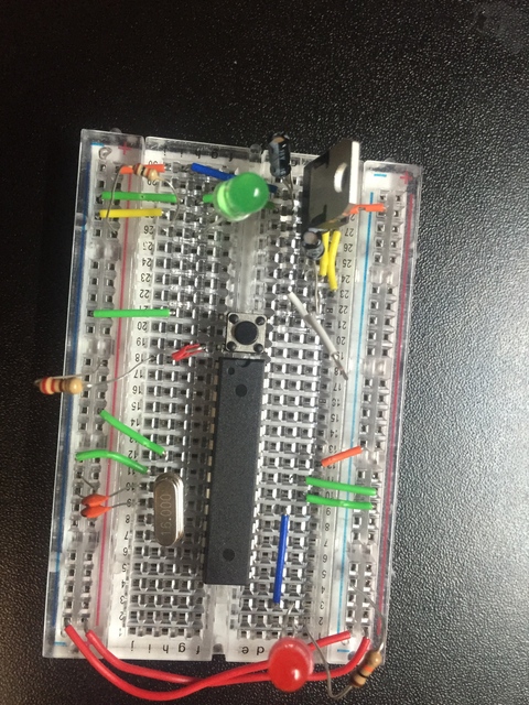
Finally wire up the reset button. Usually the momentarily open buttons are DIP and such they reach over the center of the breadboard perfectly. I place it just above the ATmega328P as it fits perfect and means the jumpers can be super short. Plug it and if the ATmega328P indent is facing away from you, place a jumper between the lower left corner and Pin 1. Remeber Pin should be connected to +5V via a resistor. The button jumper must go in between Pin 1 and the resistor. Then ground the upper left corner of the button.
The entire cirucit wired up.
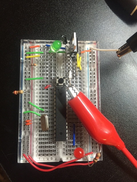
With the power plugged in. It can be a little awkward plugging the power supply into a pin on the middle of the breadboard. Just don't short it! If the Arduino Bootloader is flashed properly the red LED should start flashing. If the green LED doesn't light up you have a powering issue. If the red LED doesn't light up, start checking your wiring. The ATmega328P is not very tolerant of being shorted or having voltage placed in places they shouldn't be, but hopefully everything is wired up properly and the Red LED is flashing away.
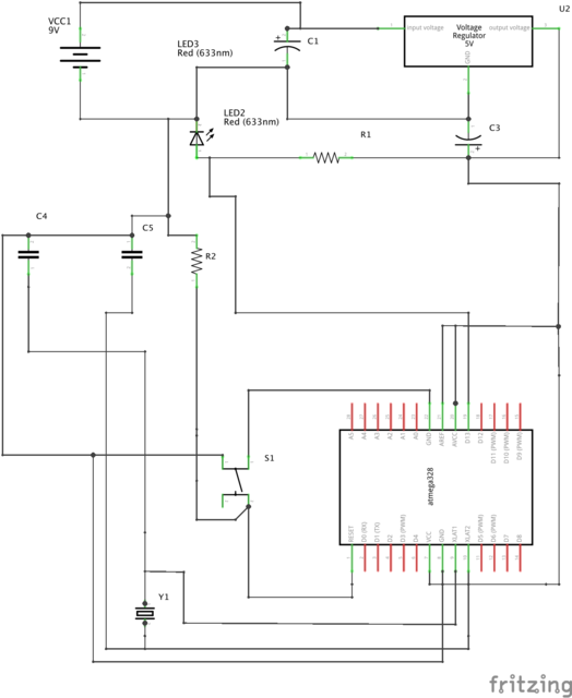
The final fritzing schematic of the breadboarduino.
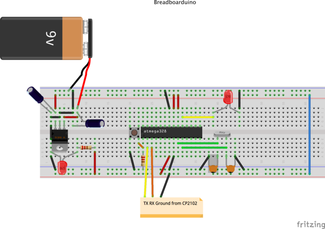
Finally a schematic of the breadboaduino. Enjoy!