Categories
Status: Active

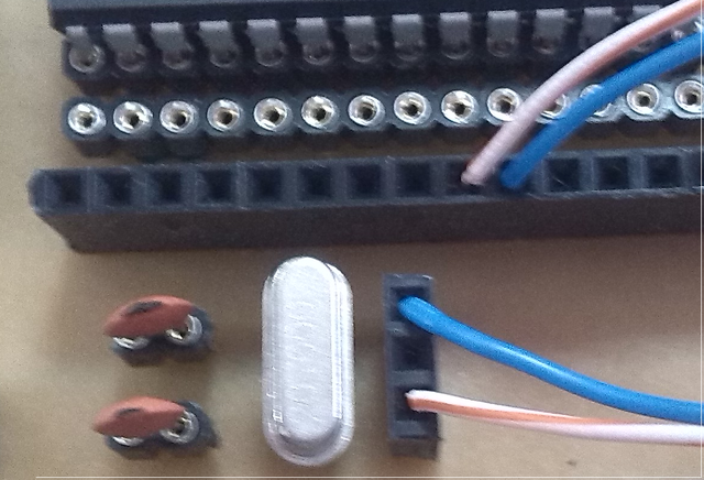
Assembled board Step 3 of 6
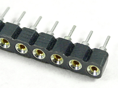
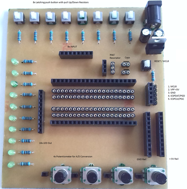
As you can see, this board emulates a breadboard by removing all wires that are difficult to track, leaving only the connection of the functional wires to the PIC.
This is how board looks fully assembled.
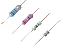
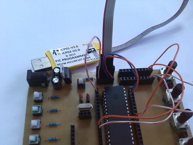
In action, with the PIC 16F887 connected, the ICSP programmer on board is ready to upload hex. As you can see, this fully emulates a classic breadboard, but is much more flexibile. All necessary wires are about 5-6 cm long. I use rigid copper wire from an ethernet cable instead of dupont. Please note that I use 1k resistors in a series with the LEDs. I do this because i don't like to look at the LED at full brightness. If you use LEDs like the water clear ultra bright type, watch your eyes, they are almost like pointing a laser light at 3 times less current than rated!
Here is the Xtal (Crystal oscilator) and capacitors plugged in. From the SIP next to the Xtal, just place two wires to the proper pins of PIC - to OSC1 and OSC2, in the case that your PIC does not have one or you wish to use some specific clock rate. Plug these in and test how it works.