Categories
Status: Active

PIC Board Step 1 of 6
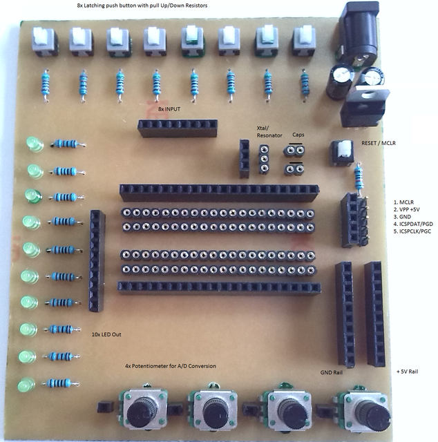
With this development board you will be able to learn how to connect PIC to the real world and test your program or application. I think this board will be great for beginners and the experienced in PIC programming.
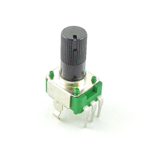
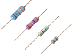
Features: 8 input with latch push button and pull up/down resistors, 10 LEDs as out, 4 potentiometers provide inputs for A/D conversion, the board has standard ICSP and a reset push button. The board is constructed with the user in mind who needs to connect every PIN of PIC on his/her own, (ie power supply to the pic and so on). Any feature or configuration can be tested (ie MCLR function ON or OFF). The board accepts all DIP packages. The most popular are DIP40 (16F887), DIP 28 (18F2550), DIP18 (16F628), DIP14 (16F688). These PIC's have internal oscillators. If you use one that does not have this, just plug in xtal and caps to the board and connect to the aproppriate pins of the PIC.
The board can be constructed very easy. I used the heat transfer technique. The Clad Board costs less than 7$ (thanks to Tayda) and with any PIC micro listed above (about 2-5$) and PICKITII clone (ebay; about 15$) - some wire to make connections - in total less than 35$!!! You be able to test and program any PIC that is currently supported by PICKITII!
Please note that you will need, of course some breadboards for other components you may have, to use in conjuction with this board.
Questions and discussion about these instructions can be found here.