Categories
Status: Active

Add resistors and pins Step 5 of 8
The resistor line up for this kit is pretty straight forward. However different resistors are needed depending on the resistance of the speakers used on the amp. I decided to add a pin header at the positive post to give some flexibility of use.
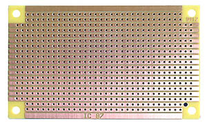
1st add the resistor on IC pin 7 and be sure to cut the strip between the resistor ends. After you add the resistor after the connection to the IC pin 8 and the negative side connection, make sure to cut the strip right after this hole. We will connect the negative post of the speaker terminal in a later step. I use a small drill bit to cut the silver strip.
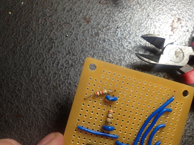
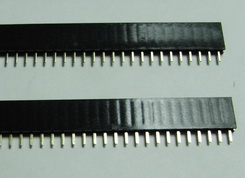
I used a razor to spit a six pin header I had laying around. Tayda carries pin headers as well.


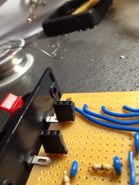
The first header is set on the 5th IC pin strip and the second pin header right on top of the speaker terminal post. Be sure to cut the connection on the strip where the terminal post and pin header are soldered to isolate the connection.
WATCH OUT - photo below shows the pin header connecting the wire post to the board. I do not recommend this. This photo is used to illustrate how the pin headers connect to the board only.