Fun With Shift Registers
A tutorial to help you understand how a shift register works.Steps
Categories
Status: Active

Step 8: More Bits Step 12 of 12
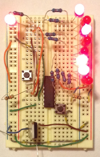
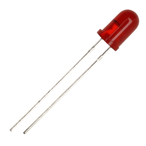
Repeat the process described in step 7 for the remaining 3 bits. When finished you will have a row of 8 LEDs.
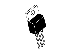
Now, connect the negetive side of the battery (black wire) to the ground rail (or middle pin on the reguator). Then connect the 9v pin to the input of the voltage regulator. (The input of the voltage regulator is the pin on the left when facing the lable.)
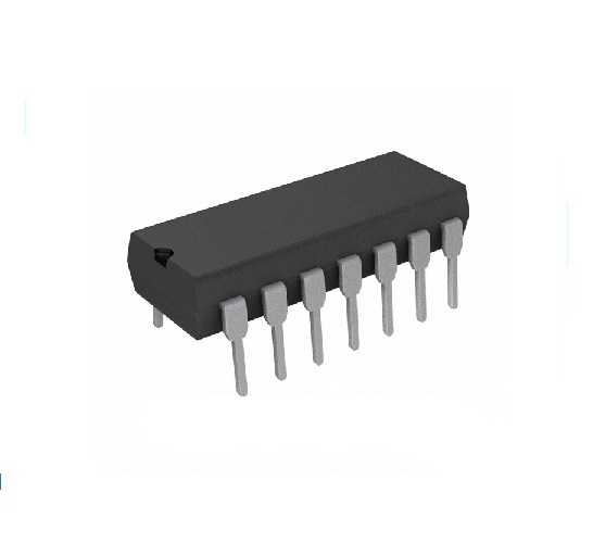
Make sure that you do not connect the 9v from the battery dirrectly to the 5v rail! This will destroy the shift register!
Once the status LED on the left is lit up, try pressing the clock button. Then try holding down the data input button and pressing the clock button. Keep playing around with button combinations until you can see how the shift register is working.