Dr Q Autowah
The Dr Q is a classic DIY autowah project that delivers a highly interactive envelope filter effect. It responds to your playing dynamics to create the distinctive choppy rhythm of the 1970s funk recordings.Steps
Categories
Status: Active

PCB assembly Step 3 of 5
Use a soldering iron with a power rating of 15-30W and 0.5-1mm diameter solder wire. Safety Note: Soldering fumes are harmful to your eyes and lungs. Always work in a well-ventilated area.

To solder, first warm up the iron and clean the tip with a damp sponge. Apply heat simultaneously to both the PCB pad and the component's leg, then melt 1-3mm of solder onto the joint. Once cooled, trim the excess component leg. A proper solder joint should be shiny and fully cover the connection without touching adjacent pads. An improper or "cold" solder joint can result in a poor electrical connection.
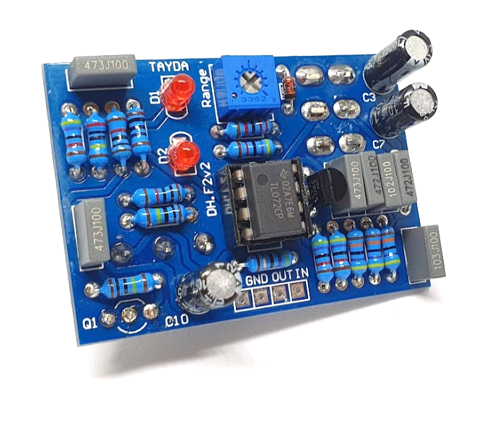
Place the components on the board according to their designated footprints. Components can be placed on either side of the PCB, but always observe the correct polarity for diodes, capacitors, and ICs. For easier assembly, solder components in order of size, starting with the smallest (e.g., resistors, diodes) and progressing to the largest (e.g., capacitors, transistors, potentiometers).
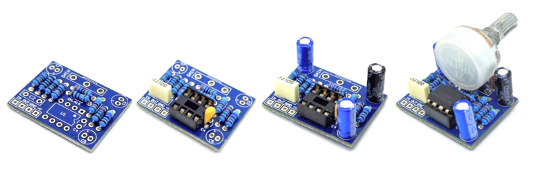
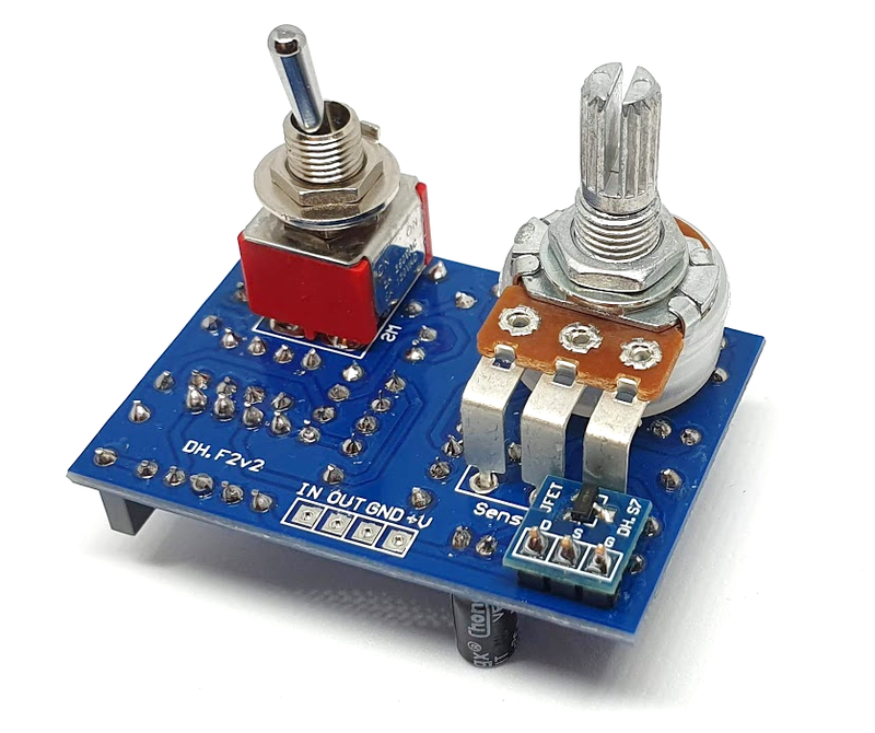
Mount the potentiometer and the switch directly on the PCB as shown in the figure below. If you are having trouble to find quality through-hole FETs, you can use SMD transistors with the SMD TRANSISTOR PCB.