Distortion Plus
The Distortion + is one of the DIY pedal classics. It has the ability to generate a great tone range between overdrive to distortion.Steps
Categories
Status: Active

Designators and components Step 2 of 5
COMPONENT LIST
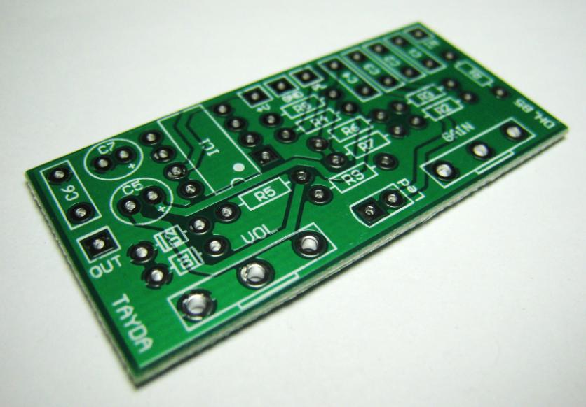
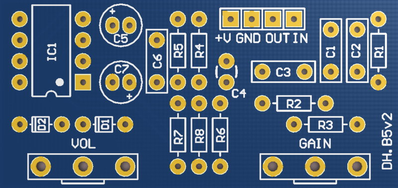
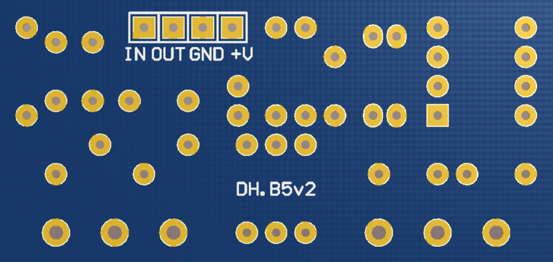
PCB
PCB DISTORTION PLUS DIY PCB GUITAR EFFECT
Capacitors
C1 1n 1NF 0.001UF 100V 5% POLYESTER FILM BOX TYPE CAPACITOR
C2 10n 10NF 0.01UF 100V 5% POLYESTER FILM BOX TYPE CAPACITOR
C3 47n 47NF 0.047UF 100V 5% POLYESTER FILM BOX TYPE CAPACITOR
C4 10p 10PF 50V MULTILAYER MONOLITHIC CERAMIC CAPACITOR
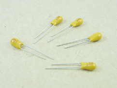
C5 1u 1UF 50V RADIAL TANTALUM CAPACITOR
C6 1n 1NF 0.001UF 100V 5% POLYESTER FILM BOX TYPE CAPACITOR
C7 1u 1UF 100V 105C RADIAL ELECTROLYTIC CAPACITOR 5X11MM
Diodes
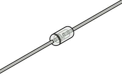
D1 1N270 1N270 GERMANIUM DIODE DO-7
D2 1N270 1N270 GERMANIUM DIODE DO-7
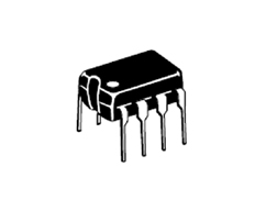
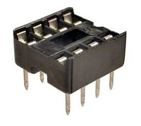
IC
IC1 TL071 TL071 OPERATIONAL AMPLIFIER J-FET PDIP-8 TL071CP
(IC1 Socket 8 PIN DIP IC SOCKET ADAPTOR)
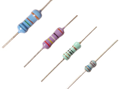
Resistors
R1 1M 1M OHM 1/4W 1% METAL FILM RESISTOR ROYAL OHM TOP QUALITY
R2 10k 10K OHM 1/4W 1% METAL FILM RESISTOR ROYAL OHM TOP QUALITY
R3 4.7k 4.7K OHM 1/4W 1% METAL FILM RESISTOR ROYAL OHM TOP QUALITY
R4 1M 1M OHM 1/4W 1% METAL FILM RESISTOR ROYAL OHM TOP QUALITY
R5 10k 10K OHM 1/4W 1% METAL FILM RESISTOR ROYAL OHM TOP QUALITY
R6 1M 1M OHM 1/4W 1% METAL FILM RESISTOR ROYAL OHM TOP QUALITY
R7 1M 1M OHM 1/4W 1% METAL FILM RESISTOR ROYAL OHM TOP QUALITY
R8 1M 1M OHM 1/4W 1% METAL FILM RESISTOR ROYAL OHM TOP QUALITY
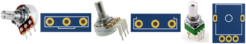
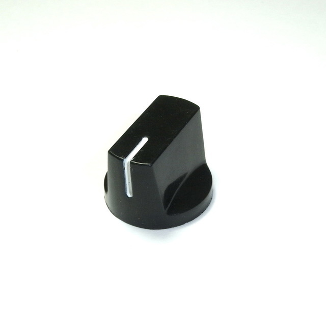
Potentiometers
VOL 100k-A 100K OHM LOGARITHMIC TAPER POTENTIOMETER
GAIN 500k-C 500K OHM C500K 500KC ANTI-LOG TAPER POTENTIOMETER
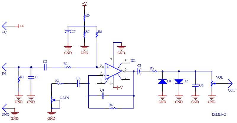
PCB
PCB SCHEMATIC
MODIFICATIONS
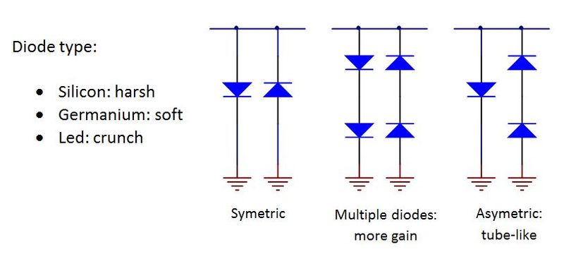
The original circuit uses two 1N270 germanium diodes. Change the diodes to obtain different distortion tones. The germanium diodes (1N60, 1N270 or 1N34A) will produce softer distortion, the silicon (1N914 or 1N4148) harder and the leds more fuzz and crunch. You can also experiment with different combinations (symmetric o asymmetric). If you want to have a versatile pedal with a diode selector, you can use a 2PDT switch or rotatory selector.
If you are using germanium diodes and the output doesn't have so much volume, you can place 2 diodes in series to increase your output level.
GENERAL DESCRIPTION OF COMPONENTS
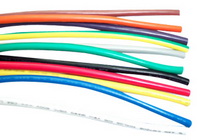
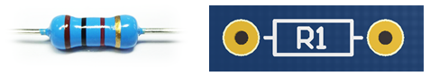
Resistors
Use a multimeter or the color bands to obtain the resistance value. Resistors do not have polarity, you can place them in any direction.
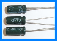
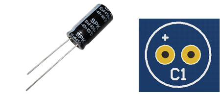
Electrolytic capacitors
Electrolytic capacitors have their value printed on them. The negative polarity pin is indicated by a white strip along the can. They also have a longer leg indicating the positive pin. The maximum voltage rating never can be exceeded, make sure you are using at least double voltage rating than your power supply. For example, if you are using a 9V power supply, use a electrolytic capacitor with at least 18V maximum voltage rating.
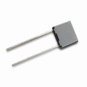
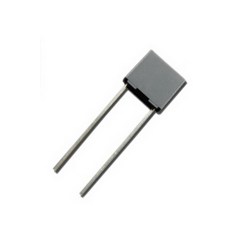
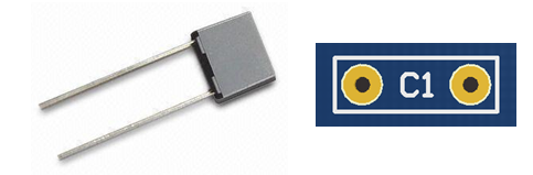
Polyester capacitors
Polyester capacitors have their value marked with three numbers. Read as picofarads (pF), the first two are the 1st and 2nd digits and the third is the multiplier code. These capacitors do not have polarity, you can place them in any direction.
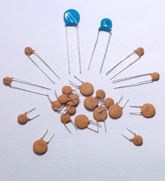
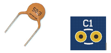
Ceramic capacitors
Ceramic capacitors have their value marked with three numbers. Read as picofarads (pF), the first two are the 1st and 2nd digits and the third is the multiplier code. These capacitors do not have polarity, you can assemble them in any direction.
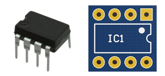
Integrated Circuits
Integrated Circuits (ICs) have their model printed on them. A notch half-circle or a dot indicates the correct position on the PCB.
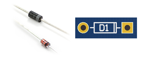
Diodes
Diodes have their model printed on them. The polarity (cathode) is indicated by the ring near the side. This ring is also marked on the PCB.
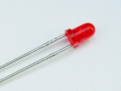
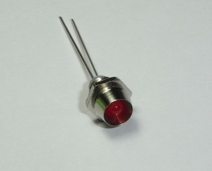
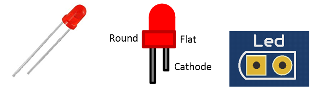
Led diodes
Led diodes have polarity, the cathode is indicated as a flat surface on the side of the diode and also it is the shorter led. On the PCB, the cathode is marked as a flat side and anode as a round side.
Potentiometers
Potentiometers have their resistance value marked on them. They are marked with A, B or C for logarithmic, linear and reverse logarithmic, respectively.