Arduino Based Memory Game - PCB
A Simon-says type game that can be easily made from scratch with a few parts and an ArduinoSteps
Categories
Created by Jeremy Wilson
Status: Active
Status: Active

The circuit diagram Step 3 of 5
Below is a schematic of the circuit for the memory game:
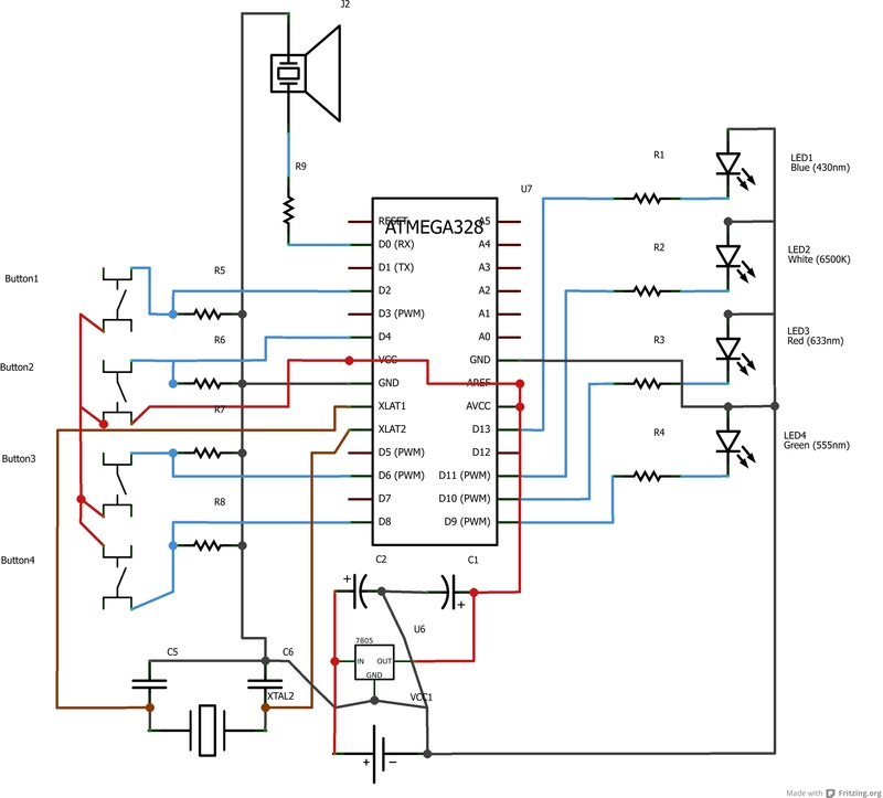
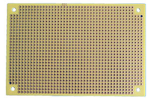
I laid it out to make soldering more convenient, with the buttons on one side of the chip, and the LEDs on the other side. This allows me to make soldier paths straight to the components, minimizing the amount of wires needed.
My color coding scheme:
- Red: 5V
- Black: 0V (neutral)
- Blue: Signal
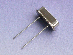
- Brown: Crystal connections
Some things to note about this diagram:
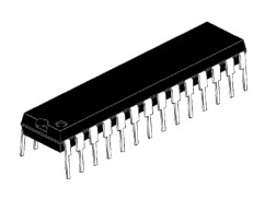
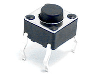
- The buttons and LEDs are attached to digital pins of the ATMega chip. The buttons are acting as digital input while the LEDs use digital output.
- The speaker is attached to a PWM pin. Tones are generated using pulse width modulation (PWM) and thus require a PWM capable pin.
- The buttons utilize pull-down resistors. See http://arduino.cc/en/tutorial/button for the reasoning behind this