Educational Post: Logic Gates
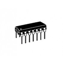
Educational posts shed some light on basic electronic functions. The goal is that they encourage everyone to learn more about individual parts and build circuits that are challenging and new so that they may eventually build more complex circuits. Let me know if you see any misinformation on any of these posts. I have played with a wide variety of circuits but I am always trying to learn new things.
Fun fact: the Apollo 11 Guidance Computer was built with 4100 Logic Gates. Yep, logic gates powered a large part of the moon landing!
Today we are going to talk about logic gates. Unless you get into the realm of quantum computing all computers work in binary so at the lowest point in a computer everything is represented as a zero or a one, true or false, high or low, 0 or 1. Logic gates facilitate this representation.
Digital Logic starts with the idea that 0 Volts = 0 and 5 Volts (or other "high" signal) = 1. So if you need the number two it would be represented by 10, or a high signal and a low signal. The more signals you have the larger the numbers. At the lowest level, this is how computers are able to work.
In todays world, most computer use transistors to build up logic gates. The first transistors were very large and developed at Bell National Laboratories in the late 40's. Over the next 70 years they have shrunk and now there are over 1.7 billion transistors on a 4th Generation Intel CPU.

A photo of the first transistor, developed at Bell Labs in the 40's.
Modern computers run almost entirely on transistors. Just as an example. A cell of SRAM to store a single bit is a combination of 6 transistors (or 4 transistors depending on the implementation). So you need a lot of transistors to even store a Byte of data. Let alone 256 Gigabytes of data!
A logical AND gate is implemented using two transistors as shown below.
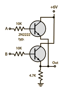
This basic implementation has two inputs. Shown at A and B and only a single Output. The Logical AND gate can be summarized as signal A AND B must be high for the output to be high. If either A or B are negative then the output is negative. This is better summarized in whats called a truth table. Truth tables summarize the underlying Boolean algebra in an easy to read format. The truth table for an AND gate is shown below:
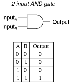
The 2 input AND gate shown with it's schematic and truth table.
Here is a summary of many logic gates and their respective truth tables:
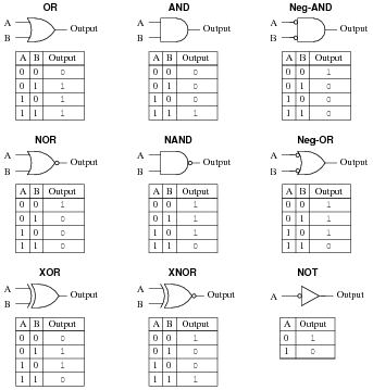
Truth tables can become quite complex, but to summarize, they in general have the inputs listed at the top, A and B in this case. Though if there were three inputs, it would be A, B and C. The final column is the output.
As the truth tables become more complex there is a subset of Boolean Algebra that shows how to summarize logic gates and their more complex behavior.
More information on how to make Logic Gates with Transistors
More Technical Information on Boolean Algebra
Links to Logic Gates at Tayda Electronics:
Many circuits have been realized with Logic Gates including complex digital circuitry. Here is an example of a clock implemented with Logic Gates!
Its your turn to find something you want to build with Logic Gates! Let us know what you find or build and post it on Tayda Kits to share with all of us.
There is a drawing error in this article!
The 2 transistor gate shown is not an AND gate, it is an OR gate!
An AND gate would have the transistors in series, both need to be turned to turn on the logic switch.
An OR gate, as shown, has the transistors parallel, so either will turn on the logic switch
AND logic table
A B OUT
0 0 0
1 0 0
0 1 0
1 1 1
..
OR logic table
A B OUT
0 0 0
1 0 1
0 1 1
1 1 1