Categories
Status: Active

Solder the bottom IC Step 4 of 8
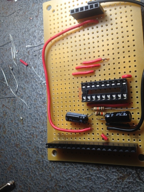
Start with the IC socket and the pin headers first. Keep in mind the bottom IC count right to left. The important pins to watch for our pin 5 and pin 6. Pin 5 is connected to the input signal and to pin7 thre the capacitor and resistor series. Pin 6 goes to the 5th and last LED which reads +6 dB. I jumped the
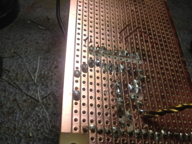
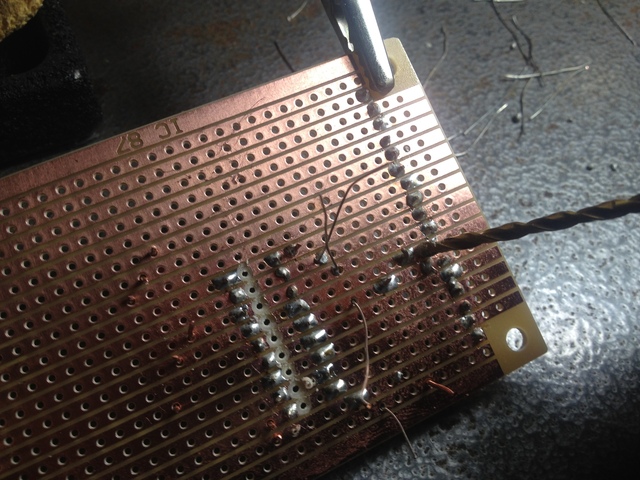
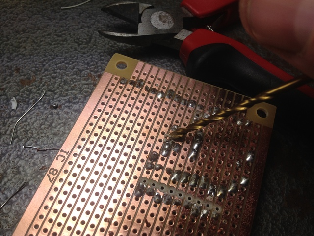
Once these have been soldered make sure to use a drill bit to cut between the two sides of the IC socket. Use a sharp point to ensure all the cooper is cut on the stripboard.
I then added a pin header two pin from the end from left two right next.
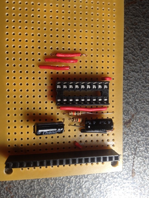
After this I added the resistors and connection wires.
I finally added the capcitors at the end and bend then over just a little so the top board would fit.
Be sure jump pin 6 on the bottom IC socket to pin 5 on the pin header.
Also make sure to cut the strip between the pin header and the connecting wire on pin 6 so that connection is not sent to top board and the strip belo the connecting wire on pin 5 so the resistor, capacitor and signal circuit is isolated.

Make sure to trim the capacitor and resistor leads once they are soldered in.
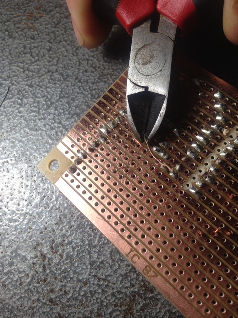
Aftrer you solder the capacitor on pin8 be sure to cut the strip between the anode and cathode of the capacitor.
Cut the connection after the signal wire is soldered on pin 8.