Categories
Status: Active

What is and where is on board? Step 2 of 6
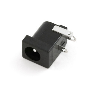
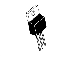
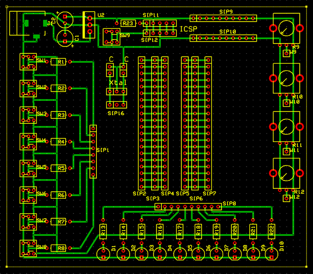
The board has DC Jack and voltage regulator for 5V.
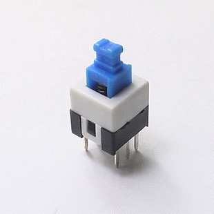
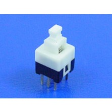
8 latching push buttons with pull up/down resistors.
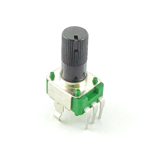
4 potentiometers - for AD conversion.
10 LEDs - representing OUT.
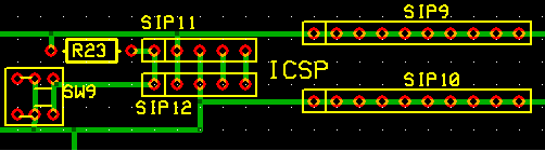
ICSP male header.
SIP headers - use to make connections and to give power to external breadboard if needed, also to connect Xtal and caps (if needed).
RESET push button.
You will need standard dupont wire (for breadboard) to connect inputs, outputs, power or xtal. Alternatively you may use coper wire from ethernet cable. Wires are solid copper, comes in 8 diferent colors and you may cut them as you like, since all wires can be short as possibile, from 3 up to 7 cm only.
SW1-8 Push button latching 6mm.
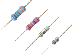
R1-R8 5K (not critical).
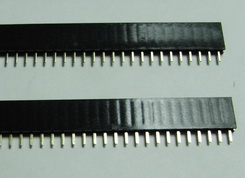
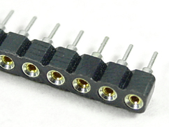
SIP1, SIP2, SIP7, SIP8, SIP9, SIP10, SIP12, SIP16 - 40 pin 2,54 mm single female header (use scalpel / razor blade to cut out pins as needed).
SIP3, SIP4, SIP5, SIP6 - 40 Pin DIP SIP IC Sockets Adaptor Solder Type.
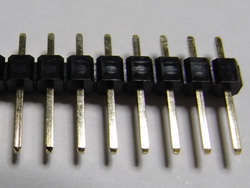
SIP11 - 40 pin male 2,54 mm header (cut out pins as needed).
W9-W12 - 40 pin 2,54 mm single female header (use scalpel / razor blade to cut out pins as needed).
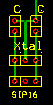
C, Xtal - 40 Pin DIP SIP IC Sockets Adaptor Solder Type (use scalpel / razor blade to cut out pins as needed).
This is where (if needed) you can attach Xtal (Crystal oscilator, 2 pins left and right );
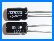
22pF (marked as C) capacitors or,
if you prefer a Ceramic resonator, they have 3 pins and are less stable in frequency than Xtal!
SIP 16 is female connector - use this to connect Xtal or ceramic resonator to PIC!
It is a good thing to leave ICSP header to your project, for this board this is must have!
ICSP header is PCB wired to isolating resistor, MCLR with push button. Use wire to connect to appropriate pins at your PIC, please note that you may program your PIC without DC power supply attached to the board. All the necessary power can be used directly from ICSP!