Fuzz Factory
The Fuzz Factory is a five-knob fuzz pedal with huge range of sound possibilities. This is classic DIY pedal project that can be built with either germanium or silicon transistors.Steps
Categories
Status: Active

Enclosure and wiring Step 4 of 5
PLACEMENT
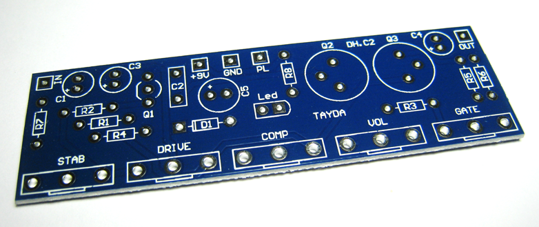
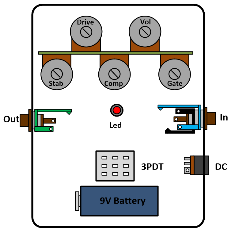
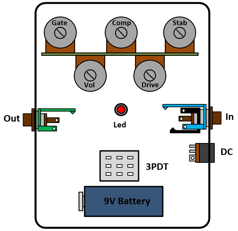
Mount the assembled PCB and the rest of the components (DC and 3.5 jack connectors, 9V battery clip, 3PDT foot switch, led...) in a metal enclosure. Connect the ground of the circuit to the enclosure (the GND of the input and output jacks are in contact with the enclosure). The following figure shows the components mounted in a 1590BB enclosure.
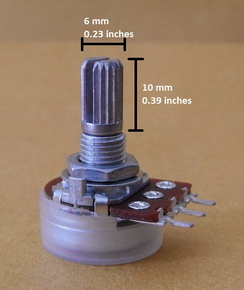
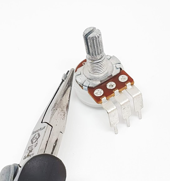
Snap off the anti-rotation tab on top of the potentiometers with a pair of flat nose spliers.
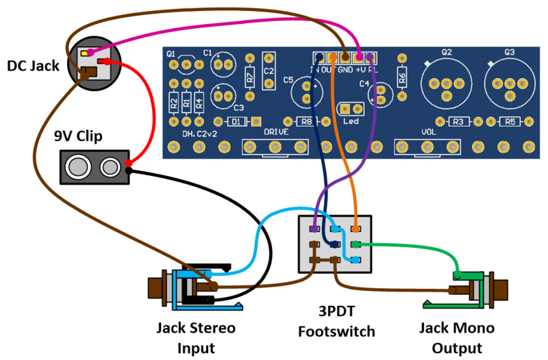
WIRING
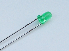
Use a 24 AWG stranded wire and connect all the elements as indicated in the following figure. No matter the order to connect the ground (GND) as far as all the components are connected. The diode led requires a current limiter resistor, you can use values in between 2.2k and 4.7k for regular leds. The following figure shows the wiring with a negative tip DC connector (standardized Boss style 2.1 mm with a negative tip orientation). The led can be directly placed on the PCB, wire the pin marked as PL to the 3PDT footswitch.
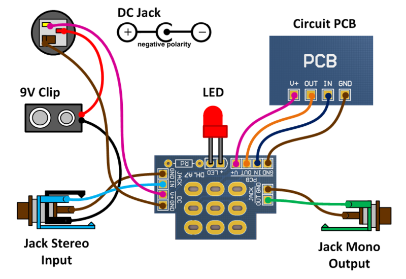
PCB FOR 3PDT FOOTSWITCH (PCB and Instructions)
The PCB for 3PDT footswitch will help you to wire all the components, keep a neat circuit and reduce the noise. This PCB also includes pads for the led and its current limiter resistor.
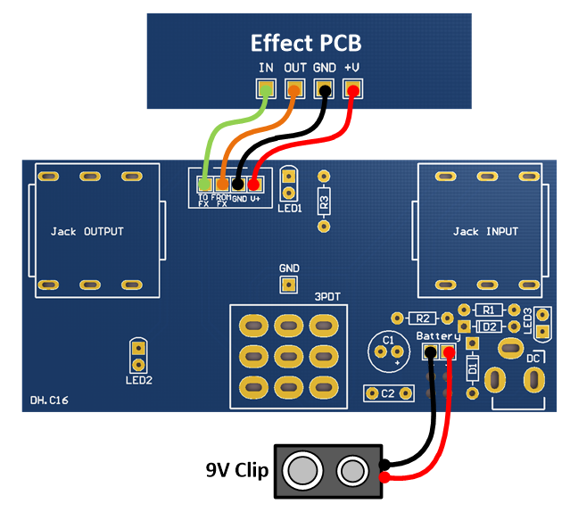
PCB FOR 1590BB ENCLOSURE (PCB and Instructions)
If you are going to use a 1590BB enclosure, this PCB will definitely help to build your pedal. Led, jacks, and footswitch are mounted on the PCB. You will only need to wire the battery clip and the effect PCB. Drilling templates are available in the attachments.
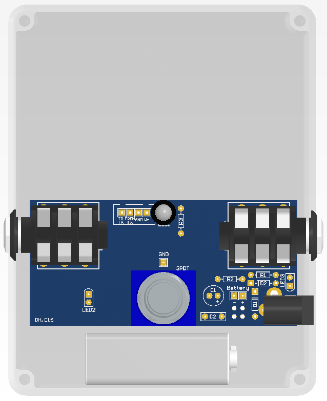
To connect the 1590BB enclosure PCB to the effect PCB you can use a 4 pin connector or solder the cables as indicated in the following figure. The PCB pins are marked as "GND" ,"+V", "FROM FX" and "TO FX". Connect "FROM FX" to the output of the effect PCB, and "TO FX" to the input of the effect PCB.
\