Status: Active

Using a USB to Serial Programmer Step 4 of 5
The CP2102 is a simple USB to Serial converter and the simplest way to describe using any USB to Serial Programmer is that they are touchy.
But it is also a good skill to have if you like playing with Arduino's as there are many situation where you may not have a dedicated USB cable. You could be using an Arduino Pro, or your ATmega could be sitting on another circuit and you want to update the firmware. Either way here are some tips and tricks.
Arduino's are nice becuase they have a lot of built in capability, the ATmega Chip is preburned with the Arduino Bootloader while the chip automatically detects when to reset itself when it has an incoming sketch from the USB port.
But on the breadboarded Arduino this is not a built in capabilty. You (yes you) have to manually press the reset button at the appropriate time.
The trick is to hit the upload sketch button in the Arduino and wait approximately 1 second (count it outload, I know from experiene that its hard to wait: One one second) and then hit the reset button on the breadboard. This works about 90% of the time.
If you press the reset button too quickly or too late the ATmega will not reset properly and you will not successfully upload your sketch.
Also some people advise repeatedly pressing the reset button multiple times, but this could result in the sketch partially uploading and then you reset it again too quickly! You only have one shot to get the sketch uploaded.
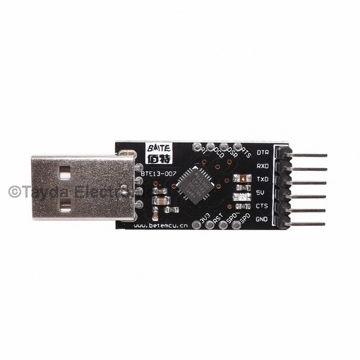
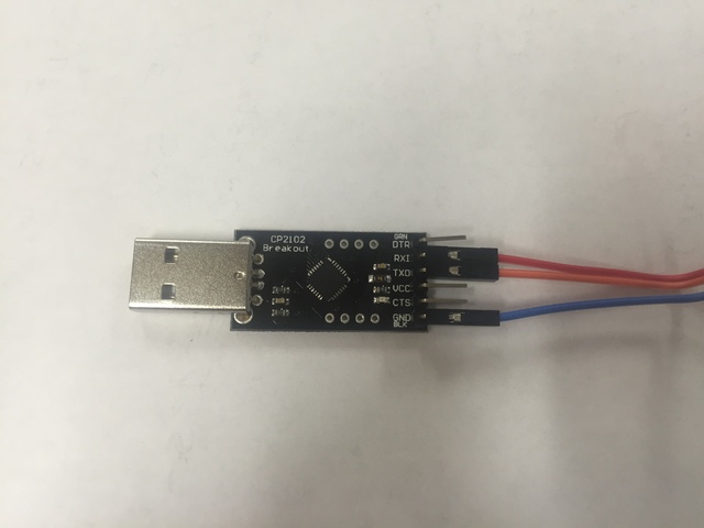
The CP2102 is a USB to Serial breakout board. Its really easy to use after you download and install the drivers.
The link to find drivers can be found here:
https://www.silabs.com/products/mcu/Pages/USBtoUARTBridgeVCPDrivers.aspx
Please follow the instructions thoroughly on how to install the drivers.
There are a few drawbacks to this breakout board though.
1. No flashing light when it uploads the sketch, often the light will flash as information is being transferred. (It usually blinks at the rate of transfer too!)
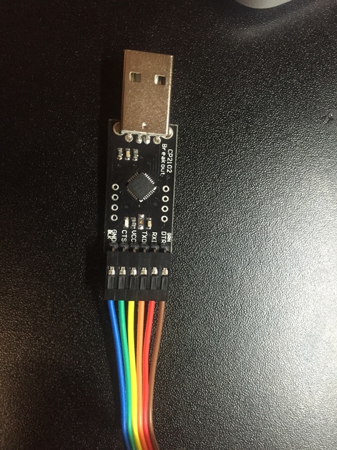
2. The provided 6 pin jumper cables are not the usual Serial Cable colors of Black - Brown - Red - Orange - Yellow - Green instead you will have to read the pinout on the break out board.
This breakout board is pinned out correctly though as DTR - RX - TX - VCC - CTS - GND. The only pins we need though are RX - TX and GND.
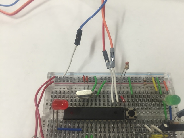
We need to hook up the CP2102 in the following manner:
RX on the CP2102 -> Pin 2 on the ATmega328P (TX)
TX on the CP2102 -> Pin 3 on the ATmega328P (RX)
Also you must make sure ground on the CP2102 is grounded to the breadboard.
The pertinent connections on the CP2102
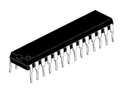
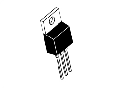
The pertinent connections on the ATmega328P. I would use a power supply other than the VCC from the CP2102. It doesn't provide enough voltage to power the LM7805 properly. A 9 Volt battery would be a great choice. A table top power supply is a great choice as well.
Now as long as the driver is installed properly you can confirm this by checking to see if an Arduino Serial Port shows up. In the Arduino IDE it is at Tools -> Serial Port and there should be a listing there. Mine is listed as /dev/tty.SLAB_USBtoUART yours may be different. You can unplug the USB and check the list and then plug it back in to ensure that it shows up properly.
Now select the sketch you want to upload and verify the sketch. Then press upload. Approximately 1 second after pressing the upload button you want to press the reset button once on the breadboard.
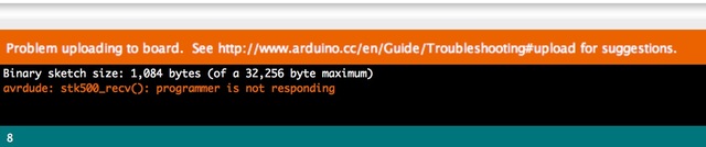
What you don't want is the error code below. This is not the programmers fault this is either pressing the reset button too soon or not waiting too long to press the reset button.